VPSS Reference Design created with HDMI2.1 Solution
/******************************************************************************
- Copyright (C) 2018 – 2021 Xilinx, Inc. All rights reserved.
- SPDX-License-Identifier: MIT ******************************************************************************/
- After completing bringing up the Vivado project and generating the xsa (link to vivado github doc)
- Generate a Vitis Project using the resulting xsa
- Export the HDMI 2.1 version 2022.1 Example Design ( driver name : v_hdmi_rxss1)
- Once loaded, export files from the src directory to the src directory of the Project. (
- Note: Extract and copy all the files from static_images.7z to src directory.
- Click on "Yes to All" if prompted to replace the files.
- Clean and build the Build the Project
- Run the project using JTAG or use the BOOT.BIN to load the app using SD-card mode.
/**************************************************************************************
Design Document
**************************************************************************************/
Video Processing Sub System Reference Design This page describes the Video Processing Subsystem core reference design, which showcases the capability and ease of use of these Xilinx LogiCORE intellectual property (IP) cores: • Video Processing Subsystem. • Video Mixer. • HDMI 2.1 Transmitter Subsystem. • HDMI 2.1 Receiver Subsystem. • HDMI PHY Controller. Table of Contents
- Overview • Reference Design Features
- Requirements • Hardware • Software • Licensing • Board Setup
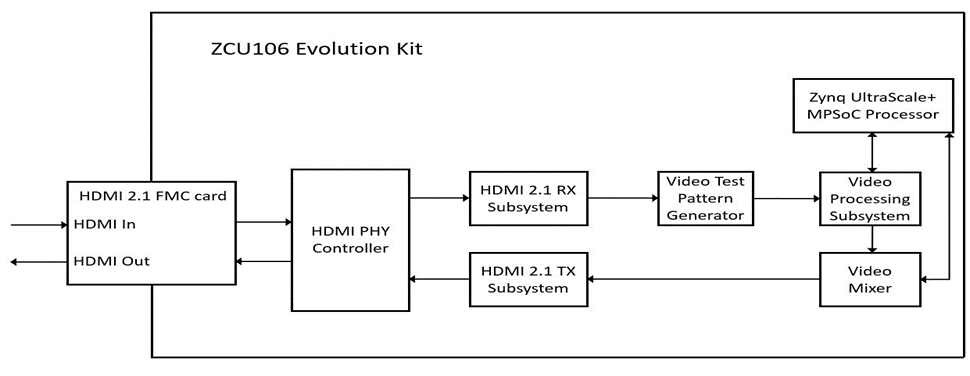
- Other Information • Verified/ Supported Resolution • Known Issues • Limitations 1 Overview The reference design uses the HDMI 2.1 RX/TX connectivity IP cores to transfer video in and out of the FPGA device. The Video Processing Subsystem and Video Mixer IP cores form the processing chain that transforms the incoming video. The design targets the Xilinx Zynq UltraScale+ MPSoC FPGA ZCU106 evaluation board. which uses the Zynq UltraScale+ MPSoC XCZU7EV-FFVC1156-2-E and the HDMI 2.1 FMC + Mezzanines TB-FMCH-VFMC-HDMI daughter card. The reference design was created with the Vivado Design Suite, System Edition 2021.2. The design also includes software built with the Xilinx Vitis 2021.2. The software runs on the ARM A53 processor subsystem and implements control and status functions. The reference design is built around the Video Processing Subsystem (V_PROC_SS), Video Mixer (V_MIX), HDMI 2.1 Transmitter Subsystem (HDMI_TX_SS), HDMI 2.1 Receiver Subsystem (HDMI_RX_SS), and HDMI PHY (HDMI_PHY) Controller cores, and uses other Xilinx IP cores to form the complete system. The input and output of the system are HDMI video streams through a HDMI 2.1 FMC daughter card that connects to the FMC HPC connector of the ZCU106 Evolution board.
The block diagram representation of this reference design is as below,
Reference Design Features The Reference Design Supports the following features:
-
Target device ZYNQ UltraScale+ MPSoC FPGA ZCU106 evaluation board.
-
Four pixel-wide interfaces.
-
Color depth fixed to 8 bits.
-
Full-fledged video processing subsystem configurations.
-
Video resolutions up to 8K at @ 30 Hz (both at input and output interface).
-
Video encoding RGB 4:4:4, YUV 4:4:4, and YUV 4:2:2
-
Supported use cases: Color space (RGB/YUV) and format (YUV 4:4:4/4:2:2) conversion Zoom mode crops a user-defined window within the input stream and scales it to panel resolution. Picture-in-picture (PIP) mode: the input stream is scaled down to a user-defined window size and displayed at the user-defined coordinates on the panel.
-
Requirements
Hardware:
The hardware requirements for this reference system are,
• Xilinx ZYNQ UltraScale+ MPSoC FPGA ZCU106 Evaluation Kit. • One HDMI 2.1 FMC + Mezzanines daughter card (TB-FMCH-VFMC-HDMI). • Two HDMI cables. • HDMI Video source that should generate 8K Video data (ex: Quantum Data, etc...) • HDMI 2.1 sink that should support 8K Resolution. • JTAG USB Platform cable or USB cable Type-A to micro-B. • USB cable with Type A to mini-B.
Software:
The software requirements for this reference design are, • Vivado Design Suite (2022.1) • Vitis Software Platform (2022.1) • Software terminals (Tera Term (or) Putty).
Licensing:
The HDMI RX and TX subsystems, Video Processing subsystem, Video Mixer, and Video Test Pattern Generator are licensed cores. Ensure that the licenses for these cores are installed for successful design compilation.
Board Setup:
The below section will provide the information on the ZCU106 board setup for running TRD.
- Connect the Micro USB cable into the ZCU106 Board Micro USB port J83, and the other end into an open USB port on the host PC. This cable is used for UART over USB communication.
- Copy the images from the reference design and insert the SD card into the SD card slot J100.
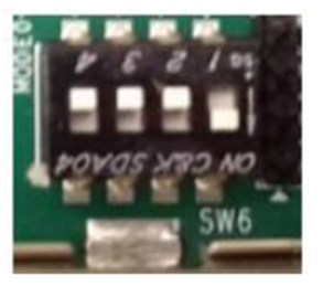
- Set the SW6 switches as shown in the below Figure. This configures the boot settings to boot from SD.
- Connect 12V Power to the ZCU106 6-Pin Molex connector.
- Connect the HDMI 2.1 FMC (TB-FMCH-VFMC-HDMI) Daughter Card to HPC connector as shown in below figure.
- Connect one end of HDMI cable to the HDMI RX connector of the FMC card and another end to HDMI source.
- Connect one end of HDMI cable to the HDMI TX connector of the FMC card and another end to HDMI monitor. Important Note: User needs to use HDMI 8K monitor to run 8K video resolutions.
- For a USB storage device, connect the USB hub along with the mouse. (Optional)
- Set up a terminal session between a PC COM port and the serial port on the evaluation board (See the Determine which COM to use to access the USB serial port on the ZCU106 board for more details)
- The below images will show how to connect interfaces on the ZCU106 board.
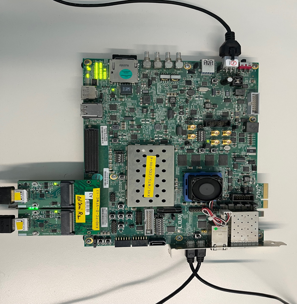
Figure: ZCU106 board setup
Determine which COM to use to access the USB serial port on the ZCU106 board. Make sure that the ZCU106 board is powered on and a micro-USB cable is connected between the ZCU106 board and host PC. This ensures that the USB-to-serial bridge is enumerated by the PC host. Open your computer's Control Panel by clicking on Start > Control Panel. Note that the Start button is typically located in the lower-left corner of the screen. Occasionally, it is in the upper left corner.
- Click Device Manager to open the Device Manager window. Note: You may be asked to confirm opening the Device Manager. If so, click YES.
- Expand Ports (COM & LPT).
- Locate the Silicon Labs Quad CP210x USB to UART Bridge: Interface 0 (COM#).
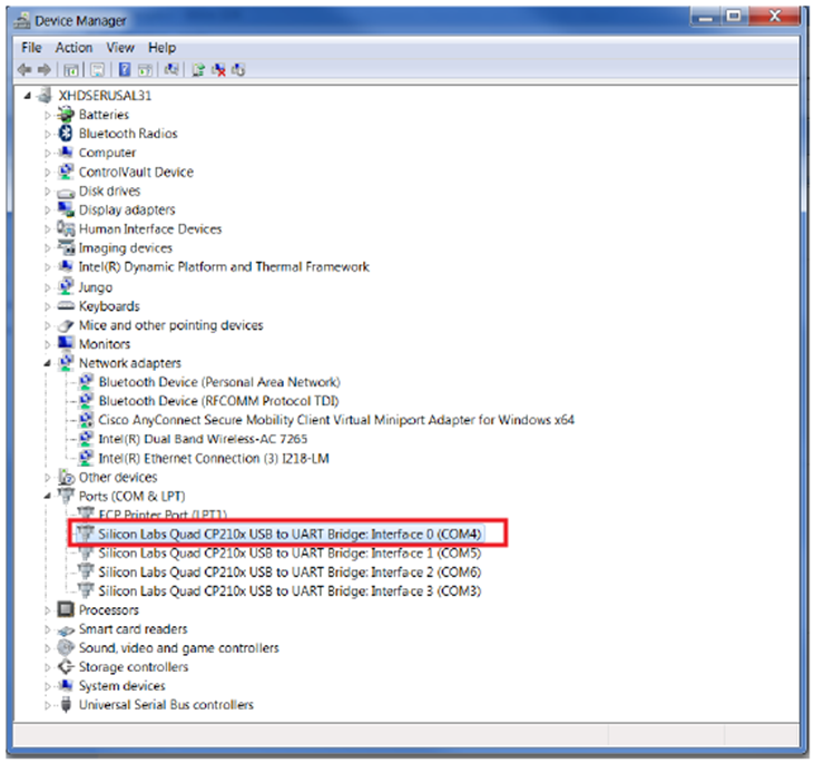
Figure: Device Manger Window
- Note down the COM Port number for further steps.
- Close the Device Manager by clicking the red X in the upper right corner of the window. Launch any Terminal application like Tera term to view the serial messages.
- Launch Tera Term and open the COM port that is associated with Silicon Labs Quad CP210x USB to UART Bridge: Interface 0 of the USB-to-serial bridge.
- Set the COM port to 115200 Baud rate, 8-bit data, no parity, 1 stop bit.
- Power ON the board which has an SD card. Switch ON SW1 to power the ZCU106 board.
Other Information:

Known Issues:
• The Vivado Design Suite on computers running Windows is sensitive to project path length. To avoid any path length issues, unzip the design to c:. Running the Reference Design There are two ways to work with the reference design: • Boot using SD-Card: Run the reference design using the precompiled binary files in the ready_for_download directory. • Boot using JTAG: Re-create the reference design in Vivado and Vitis from scratch using script files.
- Boot using SD-Card <IMG - boot config> • Copy the Boot.BIN in the SD-Card and configure the ZCU106 in SD-Card boot mode. • Insert the SD-Card and start the board.
- Boot using JTAG • After building project In a successful boot, the Serial Terminal (UART) should show the HDMI Tx and HDMI Rx configuration info. as described in figure below. When the system is first powered on, the default behavior is to have the HDMI RX stream, if present and all mixer layers are disabled by default.
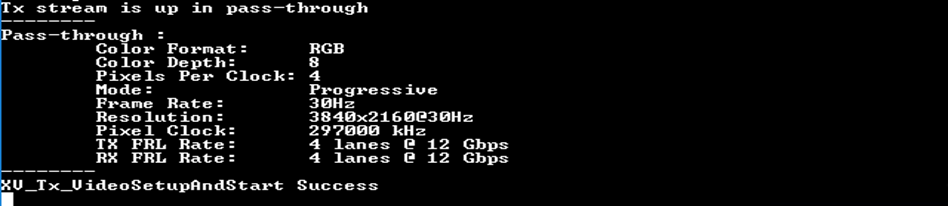
Figure: Successful Boot for a 4k resolution in FRL mode
Features and UART Menus:
The reference design demonstrates these features of the included video IP cores:
• Support for many input and output resolutions as mentioned in above Table1. • Auto detect input resolution change and configure the video pipeline. • Auto detect "No Input" condition and Pause output video. • Supports crop/zoom, and PIP functionality. • Read three video layers from memory and compose an output frame with four windows blended with master stream layer (HDMI RX stream). • Includes alternate input source (TPG) to bring up the design even when no input source is available. The reference design functionality can be accessed through the serial terminal. There are different menus available for each feature. Press 'h' key to display the Main menu, which lists all of the feature menus available in the reference design; We are describing the important few,
Mixer Menu:
Press 'm' to access the Video Mixer menu. Here the user can enable/disable the Video Mixer layers. The Mixer IP in the reference design is preconfigured with three memory layers, a logo layer, and the main streaming layer. Each memory layer has the alpha and scale feature enabled. This menu gives accessibility to exploit other features of Video Mixer namely scaling, positioning of the layers, etc.
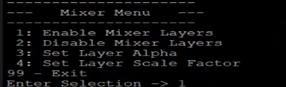
Figure: Mixer Menu
VPSS Menu:
Press 'v' to access the Video Processing Subsystem menu. Here, the user can make use of the features offered by the VPSS, • Toggle and enable Zoom/PIP mode • Configure the Zoom/PIP window • Change the background color Note: By default the zoom and pip windows are configured as • Window start co-ordinate: (0,0) • Window size: 400x400
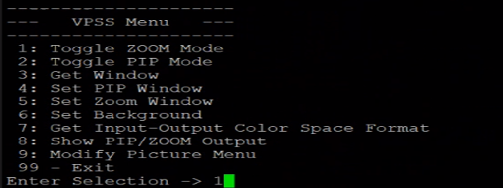
Figure: VPSS Menu
TPG Menu:
Press 't' to access the TPG menu. The TPG is used in the reference design as a secondary input stream source. The user can switch between the TPG and the HDMI RX (default) via the option in the system setup menu. Different aspects of the TPG stream can be configured from this menu. Here the user can enable/disable the Video Mixer layers. This menu primarily displays the supported patterns supported supported in the reference design.
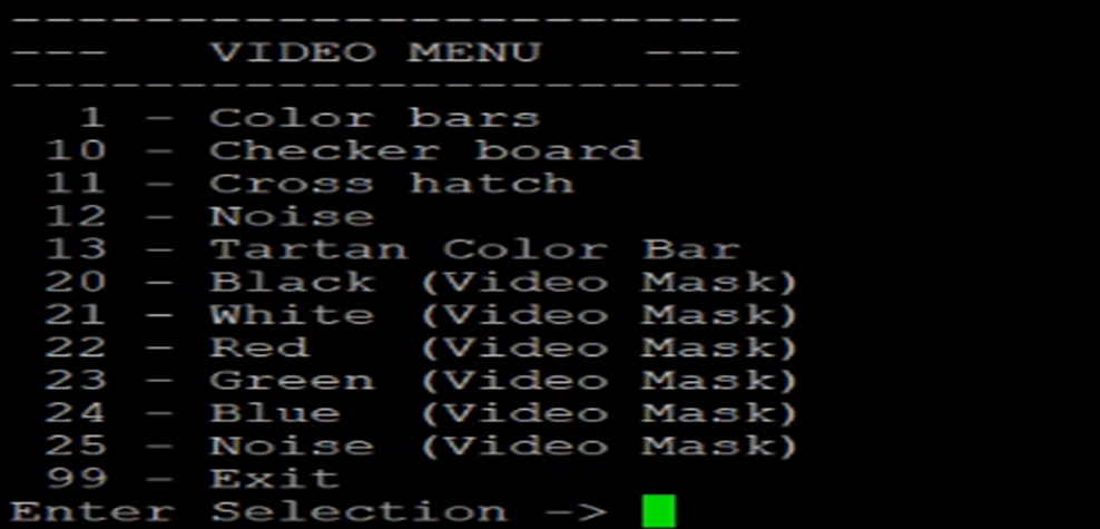
Figure: TPG Menu
Debug Menu:
The debug menu provides a software debug interface for obtaining state and register information for a core.
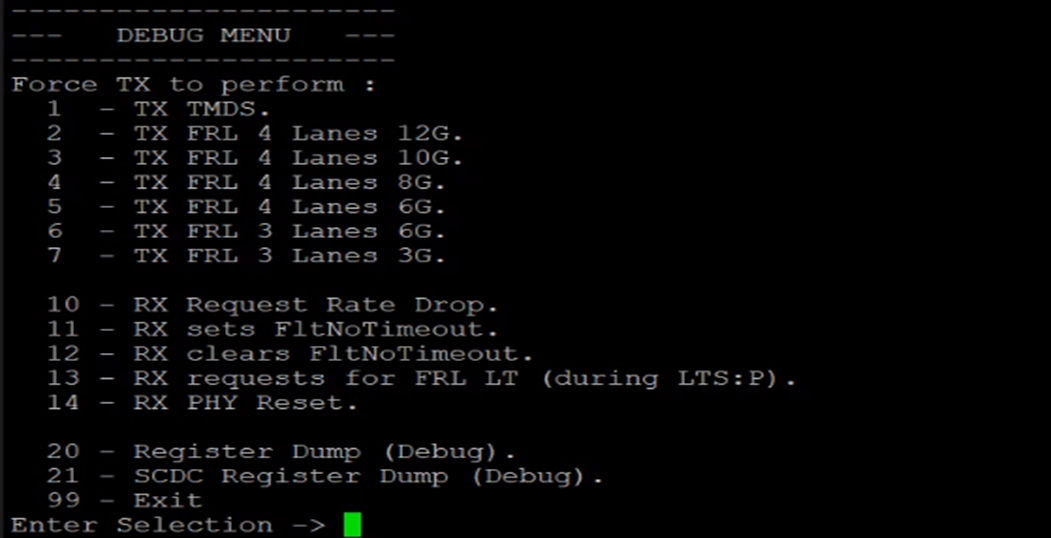
Figure: Debug Menu
Picture Menu:
The Picture Menu command provides options that impact the picture settings. By default, the picture settings impact the full image on the screen unless the picture window configurations is changed. All the operations are done on the picture/demo window (defined within the output resolution) and pixels outside the demonstration window remain as is.

Figure: Picture Menu
Apps Usage:
Users are free to change the design, add/remove features. We provide a simple use case to utilize the features of the primary IPs.
Use case 1: Showcasing PIP functionality with all Video Mixer enabled.
- Press 'v' to access VPSS. As described above (VPSS Menu), the PIP window is configured to a 400 x 400 resolution at 0,0 start coordinate.
- Toggle the VPSS to Zoom Mode to change the PIP window configurations as on the fly window configuration change is not permitted.
- Set the PIP window start X and Y coordinate to 0, 1080 respectively and set the Width and Height to 1920 and 1080 respectively.
- Toggle the VPSS back to the PIP mode.
- Press '8' apply the changes. The main layer would scale down to 1080p resolution and be positioned in the fourth quadrant of the screen.
- Press '99' to go back to the Main menu. Press 'm' to access the Video Mixer menu.
- Enable layers 1, 2, 3, and the logo layer.
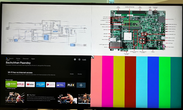
- The output should look like

Figure: Full Picture-in-Picture functionality
Use case 2: Showcasing ZOOM functionality.
- Press 'v' to access VPSS. As described above (VPSS Menu), the Zoom window is configured to a 400 x 400 resolution at 0,0 start coordinate.
- Toggle the VPSS to PIP Mode to change the Zoom window configurations as on the fly window configuration change is not permitted.
- Set the Zoom window start X and Y coordinate to 0, 0 respectively and set the Width and Height to 1920 and 1080 respectively.
- Toggle the VPSS back to the Zoom mode.
- Press '8' apply the changes. The main layer would scale up to 4k resolution and zoom the first quadrant of the streaming layer or TPG input(if enabled).
- The output should look like

Figure: Zoom functionality